-40%
Crossover PCB for the VBS-6.2 DIY speaker design - PCB Board Kit
$ 6.33
- Description
- Size Guide
Description
Custom printed circuit boards designed for the crossover of the VBS-6.2 DIY speaker design.Take the guesswork out of crossover assembly, these boards make the assembly process quick and straightforward.
The boards measure 6" x 5" and features large solder pads and copper traces for great electrical connectivity
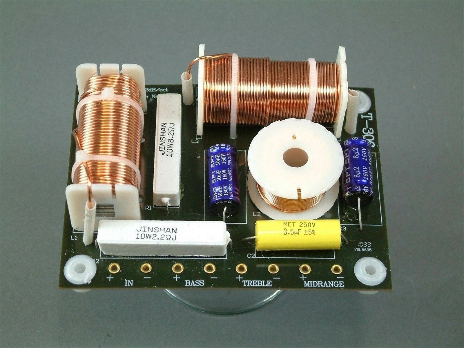
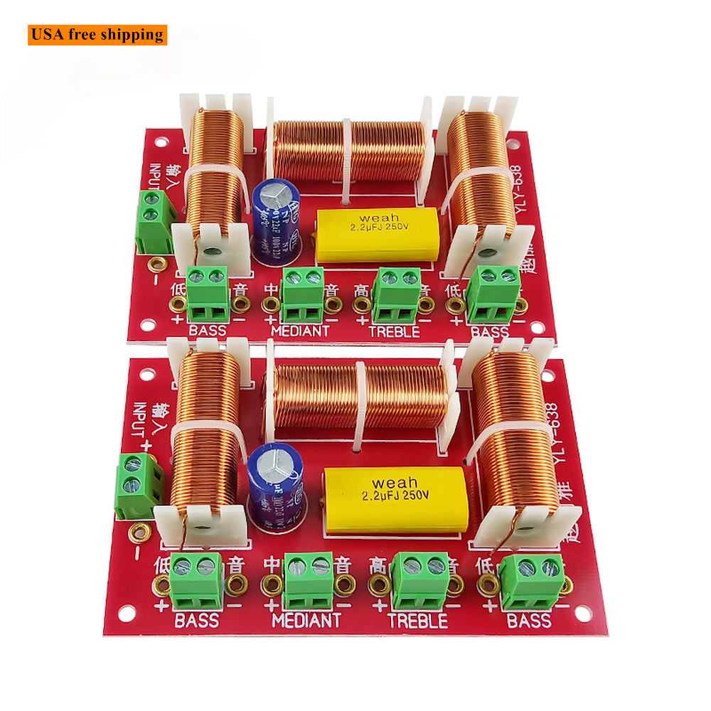
Note: Photos of the fully assembled crossover are for reference only.
*****This listing has been modified to allow you to buy the crossover boards individually in case you require an odd number, however the main photo still shows a pair. If only one is ordered you will receive a single board.*****
Includes:
1x Crossover PCB for the VBS-6.2 speaker design.
3x Terminal blocks which accept up to 12 gauge wire.
4x Snap in PCB standoffs.
4x Mounting screws (screw finish may vary).
Requires:
Crossover components for the VBS-6.2 speaker design.
Compatible components tested for fit on this PCB:
C1 - 1uF - Dayton Audio DMPC-1.0
C2 - 3uF - Dayton Audio DMPC-3.0
C3 - 1.5uF - Dayton Audio DPMC-1.5
C4 - 2.2uF - Dayton Audio DPMC-2.2
C5 - 12uF - 100V Electrolytic Non-Polar Capacitor 12uF
C6 - 17uF -
100V Electrolytic Non-Polar Capacitor 17uF
C7 - 200uF -
100V Electrolytic Non-Polar Capacitor 200uF
L1 - 0.4mH -
Dayton Audio 0.4mH 20 AWG Air Core -or- Jantzen Audio 0.4mH 20 AWG Air Core
L2 - 1.0mH -
Dayton Audio 1.0mH 20 AWG Air Core -or- Jantzen Audio 1.0mH 20 AWG Air Core
L3 - 2.0mH -
Dayton Audio 2.0mH 18 AWG I-Core -or- Erse Audio 2.0mH 18 AWG I-Core
L4 - 1.5mH -
Dayton Audio 1.5mH 18 AWG I-Core -or- Erse Audio 1.5mH 18 AWG I-Core
R1 - 9.1 Ohm - Dayton Audio DNR-9.1
R2 - 4.3 Ohm - Dayton Audio DNR-4.3
R3 - 0.5 Ohm - Dayton Audio DNR-0.51 -or- 0.47 Ohm 10W wire wound resistor
Assembly:
Glue components to the correct positions on the board (hot melt glue works great). Secure inductors with non metallic cable ties. Solder components leads to the pads on the bottom of the board. Attach wires from input and drivers and mount crossover board.


